Model 5000 Series Motorised 3 in 1 Damper

Features Model 5150
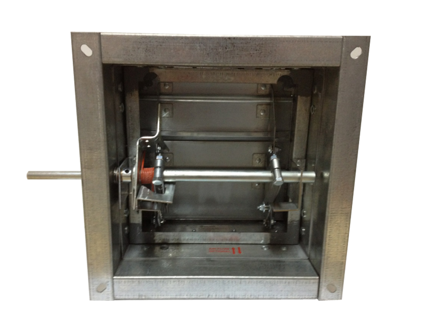
Model 5000 Motorised combination air/smoke damper. The model 5000 Prefco/Bullock motorised air/smoke damper features a 1.6mm galvanised steel fire damper casing complete with flange angles. Roll-formed galvanised steel blades are centre pivoting allowing bi-directional airflow and operation at elevated temperatures. This unique blade design is airflow tested proven to be superior to airfoil type designs, resulting in less airflow resistance. the actuator drive is a zinc plated 1/2 inch round shaft which is mechanically fixed to the plates via stainless steel pivots ensuring a smooth positive blade action at various velocities. Zero torque is required when the damper blades are in the closed position due to the patented knee action black locking and smoke sealing system.
- Optional extras available
- Minimum sizes apply

Features Model 5020-1
Model 5000-Motorised combination fire/smoke damper. The model 5020-1 Prefco/Bullock motorised smoke/fire damper is based upon the model 5000 and comes complete with the McCabe link. The McCabe link is a 68 degree C. Re-settable, re-usable bi-metallic thermal link. Once the disconnect temperature of the link is reached, the spring loaded damper blades snap closed. The patented knee action blade locking system holds the blades tightly closed. This can be overridden but only if the link has cooled to a temperature below 68 deg C. and if the actuator is still operational, to cycle the reconnection of the link to the blades. Smoke purging of the fire zone can then be achieved if the actuator power is then de-energised.
- Optional extras available
- Minimum sizes apply

Expansion gap spacers
Expansion gap spacers will come fitted to Bullock Fire Dampers to ensure the damper is centered within the penetration, they will not sag like other insulated products leading to gaps above the damper over time.
They do not completely encapsulate the damper making installation easy even in the ugliest hole!
- Tested to AS1530.4
- Patent number 726578

Tests
AS1530.4-1975
- 4hr FRL. – Sponsored investigation – 1797
- Size: 2733mm Wide x 2400mm High
- Date 13 February 1985
BS 476. Part 20-1987
- 4hr FRL. Test Number – TE87808A
UL555
- 3hr classification. (FRL) – Test number -R6189-6
EXOVA
- 2hr Plasterboard wall installation
- Assessment number -27030-03
C.S.I.R.O.
- 4hr Masonry wall installation
- 2hr Plasterboard wall installation
- Assessment number FCO – 1992
McCABE® LINK
- The McCabe re-settable, re-usable, bi-metallic thermal 68 C. Link (Standard)
- Tested to AS1890-1976. Test number-2847. (NATA-607)
- Underwriters Laboratories test (ul33) – 1976. Test number – R7569
ETDF/ETDC
TDF/TDC channels solve the problem of how to connect duct to a fire damper creating an air tight seal and still maintain a breakaway joint. However, having to notch the duct when connecting to Motorised Fire/Smoke dampers was a definite problem.
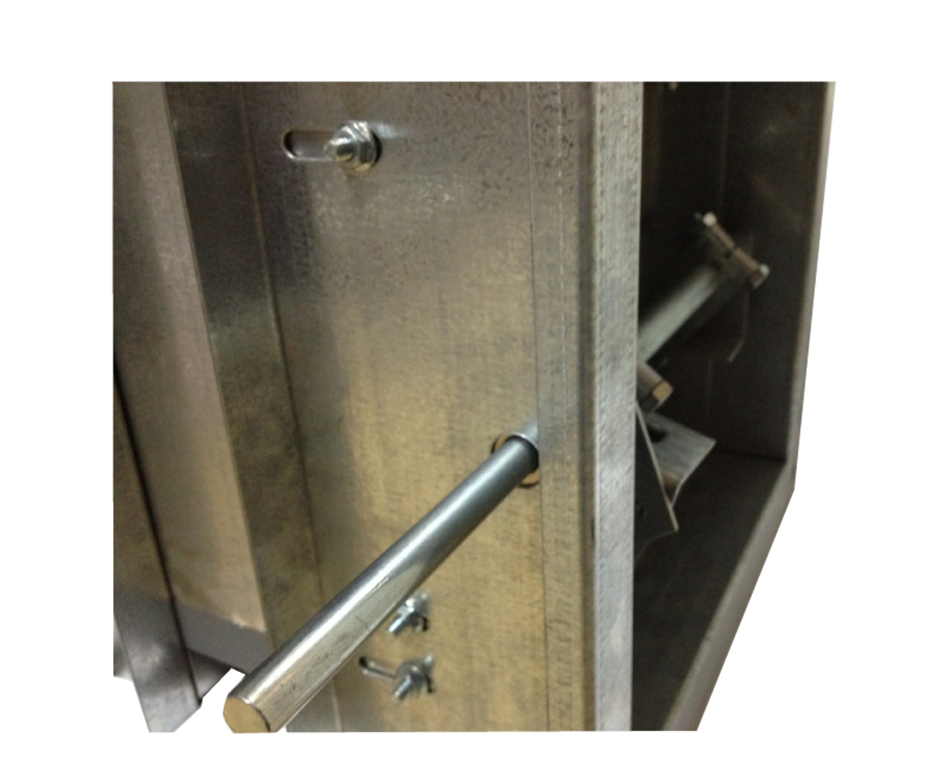
With the new ETDF/ETDC the drive shaft no longer gets in the way of the duct connection and the actuator gets mounted on the damper channel, where it should be, not on the duct. Bullock have made compliance with AS1682.2 much easier, but remember, only use nylon bolts and nylon cleats.


Ordering instructions
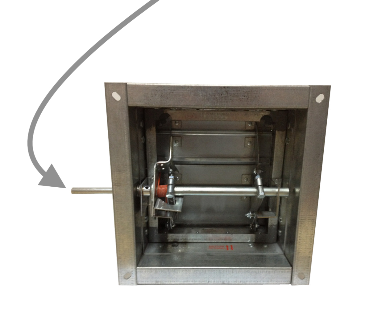
Looking at this view, the damper shown here is LEFT HAND DRIVE.
If the damper is installed in the wall and the controls (drive shaft) are in front of you, you choose what side you want to drive from, left or right.
YOUR LEFT OR RIGHT.
When ordering MFSD we require the following information:
1. Quantity
2. Damper DUCT WIDTH (blade length) dimension in Millimetres
3. Damper DUCT HEIGHT in millimetres
4. Wall thickness in millimetres
5. Style – Duct to Duct or Duct to Grille
6. Drive mounting side Left or Right
7. Options: TDF/TDC flanges and Metal expansion gap spacers
i.e. 1 x WIDTH x HEIGHT x WALL THICKNESS x STYLE x DRIVE SIDE (LEFT OR RIGHT) x OPTIONS (TDF + SPACERS)
(Left hand drive)

Installation
Instructions are critical, to comply with AS1682.2-2015. Refer to the manufacturers seperate installation instructions to suit your designed application.
Maintenance
This damper requires little maintenance once installed, refer to AS1851.6-1997 for detailed maintenance procedures.

